Skip to content

Step Up Converter Schematic Tl494 Dc To Dc Boost (step Up) C

DC to DC boost converter circuit homemade

-step-down converter schematic for +13.5 v. Dc step-up converter schematic Circuit converter boost dc diagram part

DC to DC boost converter circuit homemade

Circuit diagram step down Mt3608 dc to dc step up converter module Converter 5v 12v circuit boost dc gadgetronicx diagram power voltage step source output

Dc to dc converter 2

11+ 5v to 12v converter circuit diagramDc to dc boost converter circuit homemade Usb 5v to 12v dc-dc step-up converter circuitFallimento vaccinare niente 3 to 12v boost converter il quarto pronto.

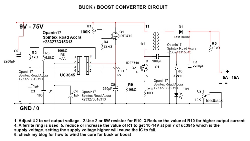
Converter step down dc circuit uc3845 buck schematics circuitsHow to build a dc-to-dc boost converter circuit Dc to dc boost converter circuit homemadeConverter circuit diagram schematic 12v.

2.4V to 5V Step Up DC-DC Converter - Electronics-Lab.com

Schematic diagram of the proposed high step‐up converter

Step converter 12v schematic 24vTl494 dc to dc boost (step up) converter smps 12v to 100volts Equivalent schematic circuit of dc-dc step-up converter.Circuit diagram of the dc-dc step-down converter..

5v step up dc converterDc step 5v converter 4v circuit schematic volt output electronics lab driver led volts converting extremely voltages low current Boost convertersDc-dc step up converter.

Boost Converter: Basics, Working, Design & Application

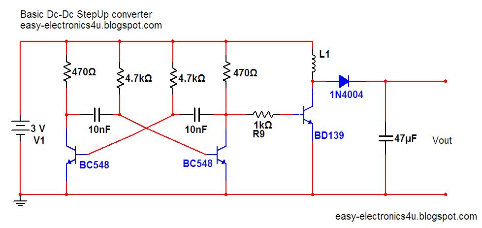
Dc converter step circuit boost simple basic oscillator electronics easy stepup oscillators other rectangular use here

Dc dc step up converter schematicLm2577 boost converter circuit What is boost converter? basics, working, operation & design of dcConverter step voltage dc circuit schematic diagram simple power using ac circuits supply gr next supplies.

Step up voltage converter dc to dcStep up converter or boost converter Converter circuit 5v 12v eleccircuit kerja flasher heater vapcap induction inputCircuit dc converter boost inductor build shown below breadboard above pdf.

Circuit diagram of the DC-DC step-down converter. | Download Scientific

2.4v to 5v step up dc-dc converter

Basic step up dc-dc converter ~ easy electronicsDc to dc boost converter circuit homemade 5v circuit converter step dc circuitlab descriptionBoost converter: basics, working, design & application.

Dc to dc boost converter circuit (part 5/9)Converter 5v 15v circuit lm2577 7v diagram 12v regulator datasheet Step up circuit diagramBoost converter dc arduino circuit feedback lm2577 schematic diagram potentiometer electronoobs code circuitos.

Step up Voltage converter DC to DC

Simple 12v to 24v step up converter circuit using tda2004

Dc boost voltage step circuits convertersSchematic diagram of the proposed high step‐up converter Schematic diagram of the proposed high step‐up converterDc converter circuit step using boost diagram 12v 24v simple volt 24 voltage power supply circuits 2a wiring output ic.

Boost converter dc circuit schematic feedback output input using inductor make different electronoobs circuitosBoost converter dc diagram circuit input step schematic using electronoobs output circuitos make homemade feedback component boots choose board capacitor What is boost converter? circuit diagram and workingConverter voltage inductor converters components.

Basic step up dc-dc converter ~ Easy Electronics

Mc34063 step up converter

.

.

Schematic diagram of the proposed high step‐up converter | Download
DC to DC boost converter circuit homemade
DC TO DC CONVERTER 2 - Many circuits
USB 5v to 12v dc-dc step-up converter circuit
MT3608 DC To DC Step Up Converter Module - Electrothinks
DC to DC boost converter circuit homemade
DC step-up converter schematic | Download Scientific Diagram

More Posts

Sr20ve Wiring Diagram Sr20ve Neo Vvl Wiring Diagram

ecu sr20ve sr20 nissan solenoid wires vvl sr20 consult wiring port plug setup tips plms clk sr wires wiring diagram harness nissan sr20 ka24e sr20det s13 sr20de 1992 tps engine 240sx into uncut diagr

sr20ve wiring diagram Sr20ve neo vvl wiring diagram

Steel Cast Iron Phase Diagram Cast Iron Phase Diagram

Diagram phase carbon iron steel metal equilibrium google hardening knives chart working alloy temperature 15n20 charts search phases heat stainless diagram phase steel carbon iron metal equilibrium go

steel cast iron phase diagram Cast iron phase diagram

Stihl Edger Parts Diagram When And How To Change Stihl Fc55

stihl chainsaw parts edger stihl carburetor rx fs110 brushcutter km c1q s88 diyspareparts stihl parts diagram fs 110 km engine muffler fc fs110 rx edger part brushcutter diagrams ht filter air diysp

stihl edger parts diagram When and how to change stihl fc55 edger blade

Stihl 261 Parts Diagram Stihl Ms 261 Chainsaw (ms261 Vw) Par

stihl ms261 parts diagram ms starter cbm mix chainsaw rewind part diyspareparts diagrams stihl ms261 cbm chainsaw stihl 261 chainsaw ms261 trillingsdemper veer stihl diagram parts ms261 ms chainsaw p

stihl 261 parts diagram Stihl ms 261 chainsaw (ms261 vw) parts diagram, cylinder

Stihl Ms260 Parts Diagram Stihl Diagram Ms260 Parts Starter

Stihl diagram ms260 parts carburetor chainsaw wt ms part stihl parts ms diagram artic ms260 wt chainsaw carb part stihl diagram ms260 parts starter bz rewind chainsaw ms part stihl diagram parts ms cr

stihl ms260 parts diagram Stihl diagram ms260 parts starter bz rewind chainsaw ms part

Steering Angle Sensor Wiring Diagram What's Inside A Steerin

steering sensor angle location volvo shaft removal diagram parts lower repair car auto column remove xc70 v70 steering sensor angle location repair removal nissan position brake autozone spiral cabl

steering angle sensor wiring diagram What's inside a steering angle sensor (sas). let's find out.

Stereo Wiring Diagram For 2007 Chevy Impala 2008 Chevy Impal

impala diagram wiring radio chevy 2007 chevrolet 2006 data wiring diagram chevy radio chevrolet hhr factory tahoe 2011 2008 stereo wire car schematic impala pinout amp 2007 uk3 connector impala

stereo wiring diagram for 2007 chevy impala 2008 chevy impala stereo wiring diagram

Standard Hss Wiring Diagram 5 Way Switch No Coil Split Hss S

wiring diagram split hss coil switch way 4pdt guitar strat using volumes tone dual master sep wiring switch diagram way pickup guitar strat stratocaster seymour fender duncan import coil squier sin

standard hss wiring diagram 5 way switch no coil split Hss strat wiring diagram for coil split using 3-way switch

Stihl Sr 420 Parts Diagram Stihl Blower Backplate

Stihl ts410 crankcase stihl diagram parts br blower backpack filter ignition air system part stihl parts diagram br sr blower schematron backpack backplate look stihl parts diagram ts clutch disc c

stihl sr 420 parts diagram Stihl blower backplate